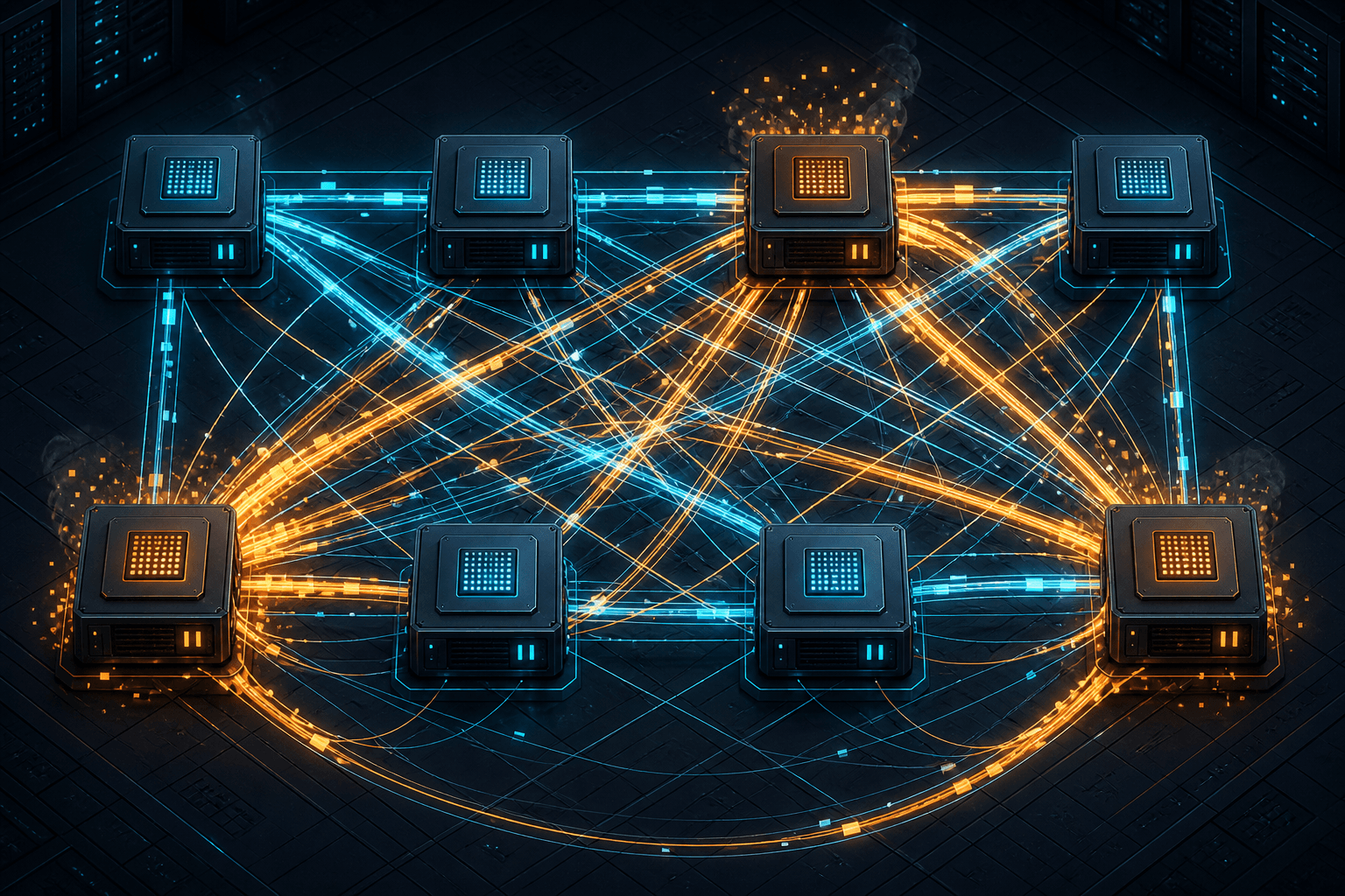
Expert Parallelism and the All-to-All Bottleneck
An examination of how expert parallelism in Mixture-of-Experts models creates an all-to-all communication bottleneck, impacting load imbalance and interconnect performance.
In the landscape of distributed large language model (LLM) training, Mixture-of-Experts (MoE) architectures have emerged as a critical scaling mechanism. By activating only a subset of model parameters for each input token, MoE allows models to grow in parameter count without a linear increase in computational cost per token. However, this efficiency comes at a steep price: the shift from compute-bound to communication-bound execution. Expert Parallelism (EP), the primary method for distributing MoE models across GPUs, introduces a severe all-to-all communication bottleneck that can dominate training time if not managed with rigorous engineering precision.
The Mechanism of Expert Parallelism
To understand the bottleneck, we must first dissect the data flow in an MoE layer. Unlike a dense transformer layer where every neuron processes every token, an MoE layer consists of expert networks. For each incoming token, a router network selects the top- experts best suited to process that token. In a typical configuration, is small (e.g., 2 or 4), while is large (e.g., 64 or 256).
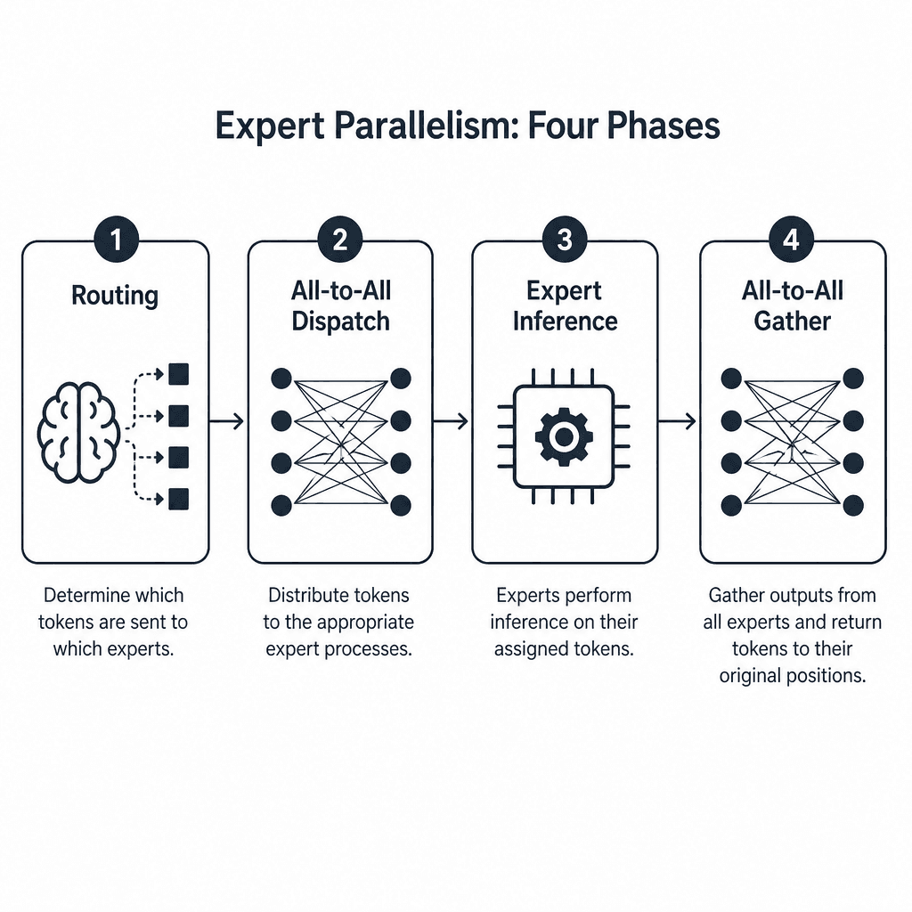
In expert parallelism, these experts are sharded across GPUs. Each GPU holds a subset of the experts, denoted as . The forward pass proceeds in four distinct phases:
- Routing: Each GPU processes its local tokens and determines which remote GPUs hold the experts required for those tokens via moe routing logic.
- All-to-All Dispatch: Tokens are packed and sent from source GPUs to destination GPUs based on the routing decisions. The tensor shape here is typically , but it is repacked into a sparse format where each row corresponds to a token destined for a specific remote expert.
- Expert Forward Pass: Each GPU performs matrix multiplications using only the tokens assigned to its local experts. This stage is compute-intensive but isolated to local memory.
- All-to-All Gather: Results are sent back to the source GPUs to be combined and passed to the next layer. The gathered tensor shape returns to , reassembled in the original token order.
This structure contrasts sharply with Tensor Parallelism (TP), where layers are split horizontally and communication is typically all-reduce (summing gradients) or all-gather (collecting parameters). In TP, the communication pattern is static and predictable because the split points are fixed at graph construction time. In EP, the communication pattern is inherently all-to-all because the destination of each token is dynamic and determined at runtime by the router. This dynamic nature means the network must handle irregular, unpredictable message sizes and destinations, making it significantly harder to optimize than the regular, bulk transfers of TP.
The All-to-All Communication Pattern
The core challenge lies in the all-to-all operation. Consider a training cluster with 8 GPUs (GPU 0 through GPU 7) and 64 experts. If each GPU holds 8 experts, the routing logic for a batch of tokens becomes complex.
Let us trace a concrete scenario. Token arrives at GPU 0. The router determines that should be processed by Expert 55. Expert 55 resides on GPU 6. Therefore, GPU 0 must send a message containing 's hidden state to GPU 6. Simultaneously, GPU 0 might need to send Token to GPU 3, and Token to GPU 0 itself (if Expert 5 is local).
This creates a scatter-gather pattern. Every GPU must construct a message buffer containing payloads destined for every other GPU. The volume of data exchanged is proportional to the number of tokens multiplied by the hidden dimension size, divided by the number of GPUs. For massive batches, this volume is significant. Unlike the predictable, regular all-reduce operations in dense models, the all-to-all packets in MoE are irregular in size and timing. This irregularity prevents efficient use of network hardware, which thrives on regular, bulk data transfers. Furthermore, the moe routing decisions are made independently per token, meaning there is no global scheduling to optimize the network flow, leading to potential congestion hotspots.
Load Imbalance and Tail Latency
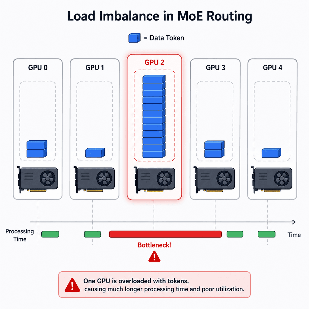
Load imbalance is a secondary, more insidious problem introduced by the dynamic nature of MoE. In an ideal scenario, tokens would be distributed evenly across all experts. However, in practice, certain experts become "hot spots." This can happen due to data distribution biases in the training corpus or early-stage training dynamics where some experts capture more semantic patterns.
If Expert 55 is heavily favored, GPU 6 will receive a disproportionate number of tokens. While GPU 0, 1, and 2 might finish processing their assigned tokens in 10 milliseconds, GPU 6 might take 50 milliseconds. Because MoE training is synchronous, the entire batch must wait for GPU 6 to complete its computation before the next layer can begin. This tail latency dominates the global step time.
The communication bottleneck exacerbates this. GPU 6 not only has more compute work but also receives more incoming messages. If the network interface card (NIC) or NVLink switch is saturated, GPU 6’s receive buffer fills up, causing backpressure that can stall the entire cluster. This is particularly problematic in large-scale clusters where network bandwidth is finite and contention is high. The moe routing algorithm's inability to perfectly balance load in real-time means that some GPUs will consistently lag, reducing the overall utilization of the cluster.
Interconnect Constraints and Mitigation
The severity of the all-to-all bottleneck is directly tied to the interconnect technology. In clusters connected via InfiniBand or RoCE (RDMA over Converged Ethernet), the network is optimized for high bandwidth but can suffer from packet loss and retransmissions under the irregular load of MoE. NVLink, used within a single node (e.g., 8x A100s), offers much higher bandwidth and lower latency, making intra-node EP more efficient than inter-node EP.
Engineers employ several strategies to mitigate these issues:
- Load Balancing Losses: Adding a penalty term to the loss function that encourages uniform expert utilization. This prevents experts from becoming too hot but adds computational overhead and can degrade model quality if over-regularized.
- Expert Placement: Static assignment of experts to GPUs based on historical usage patterns. This reduces the randomness of communication but lacks adaptability to changing data distributions.
- Bucketing and Packing: Grouping multiple tokens into larger packets to amortize network overhead. This improves throughput but increases memory pressure and latency jitter.
- Hybrid Parallelism: Combining EP with Tensor Parallelism and Pipeline Parallelism. For example, using TP within a node for expert computation and EP across nodes for expert distribution. This balances the communication load but increases architectural complexity.
The choice of interconnect dictates the feasible scale of EP. Clusters with high-bandwidth, low-latency fabrics can support larger numbers of experts and higher sparsity levels. Conversely, clusters with limited bandwidth must restrict the number of active experts or reduce the batch size, limiting overall throughput. Effective moe routing strategies that consider network topology can also help distribute traffic more evenly, reducing the pressure on any single link.
Conclusion
Expert Parallelism is essential for scaling MoE models beyond the memory limits of single GPUs. However, it transforms the training pipeline into a communication-heavy workload where the all-to-all operation is the primary bottleneck. Load imbalance and interconnect constraints further complicate performance, requiring careful engineering to ensure that the theoretical efficiency of MoE is realized in practice. As models continue to scale, optimizing the interplay between routing logic, network hardware, and parallelism strategies will remain a critical frontier in distributed systems engineering.
Related posts
Tensor, Pipeline, and Expert Parallelism Compared
A comparison of tensor, pipeline, and expert parallelism strategies for scaling large language models and MoE architectures.
How Mixture-of-Experts Changes Your Serving Math
An examination of how Mixture-of-Experts (MoE) architectures alter serving math, focusing on active parameters, routing overhead, and infrastructure implications for ML engineers.
