Tensor and Pipeline Parallelism in vLLM
Explore how vLLM uses tensor and pipeline parallelism to scale large language models across multiple GPUs efficiently.
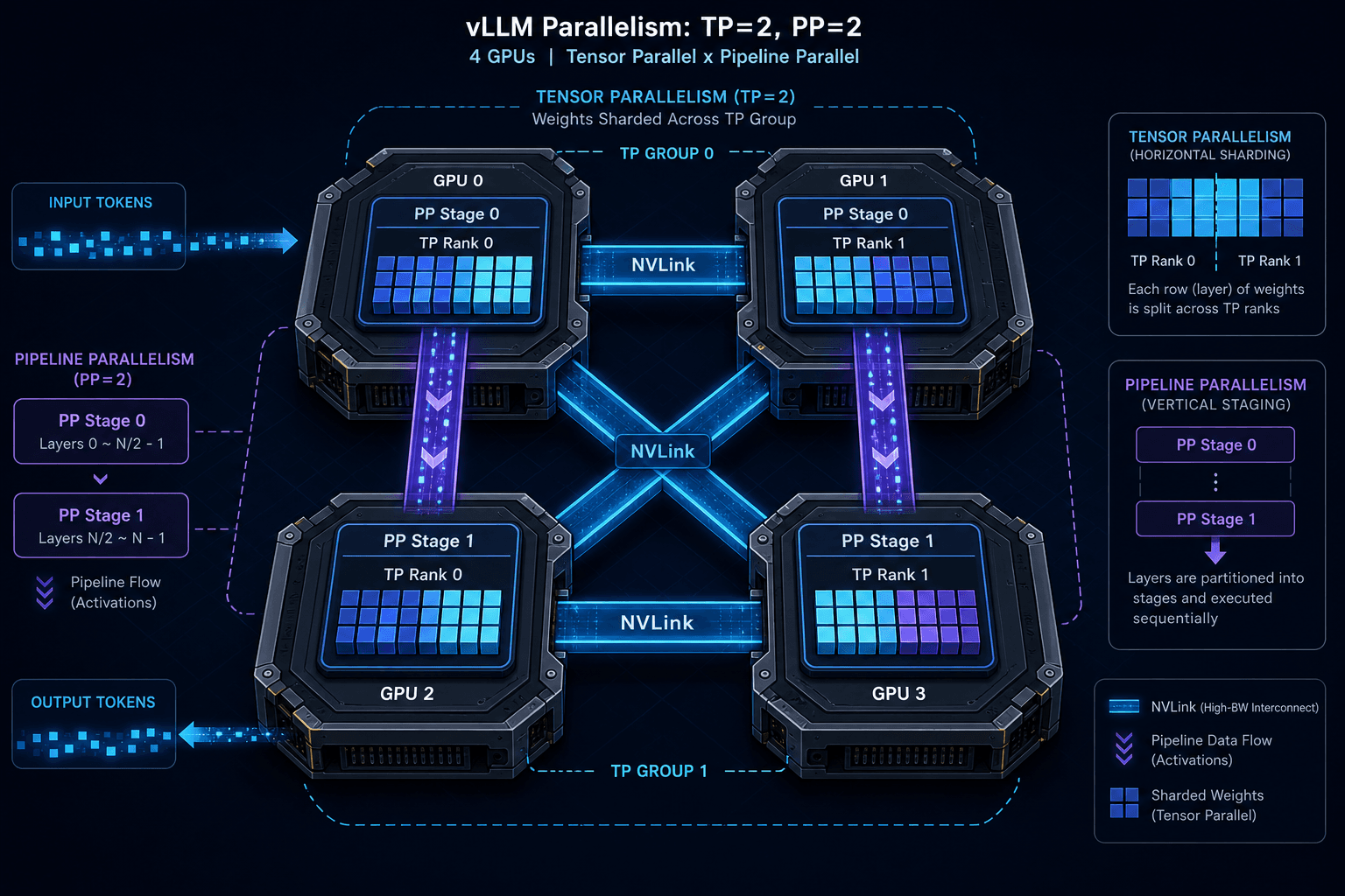
Deploying Large Language Models (LLMs) like Llama-3-70B or Mixtral 8x7B requires navigating a fundamental hardware constraint: VRAM capacity. A single modern GPU, such as the H100 with 80GB of memory, cannot hold the weights of these models, nor can it process the KV-cache for long contexts without exhausting resources. vLLM solves this not by changing the model architecture, but by distributing the computation and memory state across multiple GPUs using two distinct parallelism strategies: Tensor Parallelism (TP) and Pipeline Parallelism (PP). Understanding how these mechanisms interact is critical for infrastructure engineers aiming to maximize throughput while minimizing latency.
The Mechanism of Tensor Parallelism
Tensor Parallelism operates at the level of individual neural network layers. It is designed to handle models whose weight matrices are too large to fit into the memory of a single GPU. In vLLM, TP splits the linear transformations within a layer across a group of GPUs, typically referred to as a "TP group."
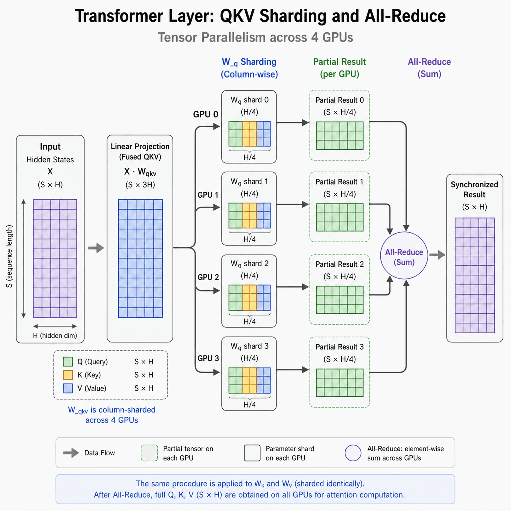
Consider a standard Transformer layer containing a Query-Key-Value projection matrix of shape . If we use a tensor parallel size of , vLLM does not store the full matrix on any single GPU. Instead, it shards the columns of across the four GPUs. Each GPU holds only $1/4$ of the weights.
When a forward pass occurs, each GPU computes its partial result independently. However, because the final output of the linear layer must be the sum of these partial results, the GPUs must synchronize. This is achieved through an All-Reduce collective operation. In the context of vLLM, this synchronization is not a simple CPU-mediated broadcast; it is a high-speed, memory-to-memory operation.
For attention mechanisms, the sharding is more complex. The query, key, and value projections are sharded by attention head across GPUs, and the output projection requires an all-reduce to combine the partial results. vLLM handles this by ensuring that the reduction happens efficiently over the NVLink interconnect. Without TP, a 70B model would simply fail to load. With TP=4, the model fits, but the compute is distributed, requiring constant synchronization between the GPUs in the TP group.
Pipeline Parallelism: Staging the Compute
While Tensor Parallelism solves the memory bottleneck per layer, it does not solve the utilization bottleneck when the model is so large that even with maximum TP, the number of GPUs required exceeds the physical cluster size, or when we need to overlap computation with communication more aggressively. This is where Pipeline Parallelism (PP) enters.
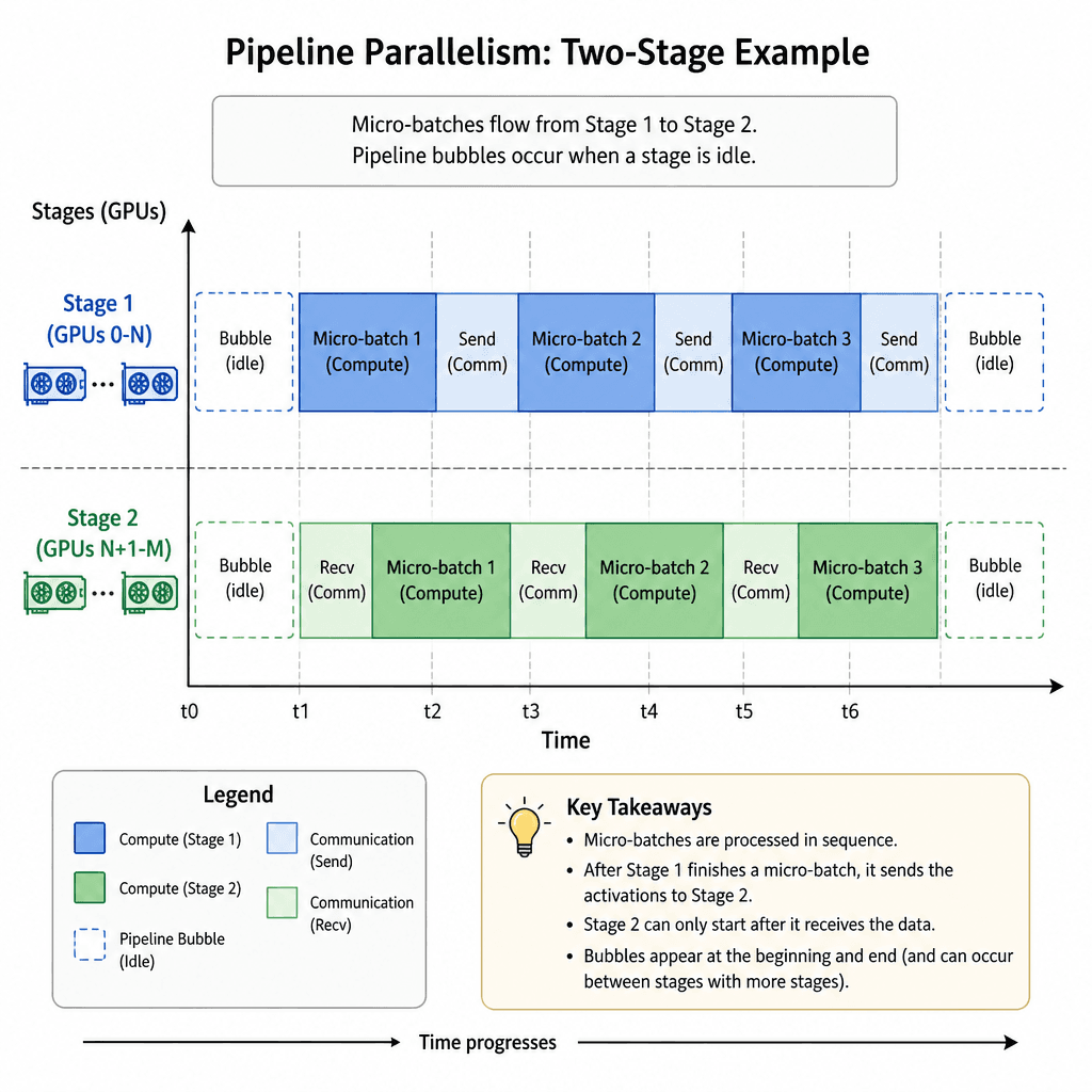
Pipeline Parallelism divides the model's layers into sequential stages. If a model has 80 layers and we set pipeline_parallel_size=2, one group of GPUs handles layers 0–39, and the second group handles layers 40–79. Data flows from the first stage to the second stage layer-by-layer.
In vLLM, PP is implemented alongside TP. The parallelization strategy is hierarchical: the outer loop is usually PP (dividing the model depth), and the inner loop is TP (dividing the width within each layer). This creates a grid of workers. For example, with tensor_parallel_size=2 and pipeline_parallel_size=2, you have four GPUs arranged in a grid.
The key challenge with PP is pipeline bubble — idle time where a GPU waits for the previous stage to finish processing a micro-batch. vLLM mitigates this by using continuous batching and carefully scheduling micro-batches. However, PP introduces latency overhead because the output of one stage must be transferred to the next. In vLLM's architecture, this transfer is handled by the ParallelState manager, which coordinates the P2P (Point-to-Point) communication between the senders and receivers in adjacent pipeline stages.
The Communication Stack: P2P and NCCL
The efficiency of both TP and PP in vLLM hinges on the underlying communication library. vLLM relies heavily on NCCL (NVIDIA Collective Communications Library) for collective operations like All-Reduce (used in TP) and Send/Recv (used in PP).
However, standard NCCL usage over TCP/IP is far too slow for LLM inference. vLLM optimizes this by leveraging NVLink and NVSwitch technologies. When GPUs are connected via NVLink, they share a high-bandwidth, low-latency memory bus. vLLM enables P2P (Peer-to-Peer) access, allowing one GPU to read and write directly to the memory of another GPU. Crucially, while the data path is CPU-bypassed (zero-copy) to minimize latency, the control path—including buffer initialization, synchronization primitives, and error handling—is still managed by the host CPU. This hybrid approach ensures that the heavy lifting of data movement is offloaded from the CPU cores, but the orchestration remains robust and controllable.
For TP, NCCL performs an All-Reduce operation. In a typical H100 cluster with NVLink Switches, bandwidth can exceed 900 GB/s, allowing for near-instantaneous aggregation of partial results compared to PCIe-based interconnects. For PP, vLLM uses non-blocking sends and receives to overlap communication with computation. While one stage is computing the next layer's activations, it is simultaneously sending the current layer's outputs to the next stage via P2P NVLink. This overlap is critical for hiding latency.
# Conceptual representation of vLLM's parallel setup (pre-0.6.0 API)
from vllm import LLM

llm = LLM(
    model="meta-llama/Meta-Llama-3-70B",
    tensor_parallel_size=4,      # Splits weights across 4 GPUs
    pipeline_parallel_size=1,    # No PP in this example
    gpu_memory_utilization=0.95,
    trust_remote_code=True
)
In the example above, vLLM initializes a TP group of 4 GPUs. During the forward pass, when the attention mechanism's output projection requires combining partial results across GPUs, vLLM triggers an NCCL All-Reduce operation over the NVLink fabric. This operation is highly optimized, leveraging shared memory and ring algorithms within NCCL to minimize overhead. If the GPUs were connected only via PCIe or Ethernet, the synchronization overhead would dominate the computation time, making TP ineffective.
Practical Configuration and Tradeoffs
Choosing the right parallelism configuration is a trade-off between memory capacity, compute utilization, and communication overhead.
- Tensor Parallelism (TP): Best for fitting large models into memory. It scales well with NVLink bandwidth but adds synchronization latency. If you have a cluster of A100s with NVLink, TP is highly efficient. If you are using GPUs connected only via PCIe, TP overhead may outweigh benefits for smaller models. Benchmarks suggest that TP=2 or TP=4 on NVLink-connected clusters can achieve near-linear scaling for large batch sizes, whereas TP>8 often hits diminishing returns due to all-reduce contention.
- Pipeline Parallelism (PP): Best for scaling beyond the memory limits of TP alone or when using clusters with slower interconnects where overlapping communication is more valuable than tight synchronization. PP introduces pipeline bubbles, which reduce theoretical peak throughput. To mitigate this, vLLM uses chunked prefill and continuous batching to keep all stages busy. However, PP increases end-to-end latency because the request must traverse multiple stages sequentially.
vLLM allows you to combine these using the --tensor-parallel-size and --pipeline-parallel-size CLI flags. The total number of GPUs used is the product of these two sizes.
# Example: Running Llama-3-70B on 8 GPUs
# 4 GPUs for TP (memory split), 2 GPUs for PP (layer split)
vllm serve meta-llama/Meta-Llama-3-70B \
    --tensor-parallel-size 4 \
    --pipeline-parallel-size 2
Engineers must also consider GPU topology. vLLM attempts to auto-detect the topology using nvidia-smi, but manual configuration may be required if the GPUs are not evenly connected via NVLink. Misconfiguring TP groups to span across PCIe bridges can result in severe performance degradation due to increased latency in All-Reduce operations. A common best practice is to keep TP groups within a single NUMA node or NVLink domain whenever possible.
Conclusion
vLLM’s efficiency in serving LLMs is not just about its scheduler, but about how it harnesses distributed hardware. Tensor Parallelism allows models to exceed single-GPU memory limits by sharding weights, while Pipeline Parallelism distributes layer computation across stages. Both rely on low-latency P2P communication over NVLink to minimize the overhead of synchronization. For infrastructure engineers, understanding this mechanism is essential: optimizing for throughput requires balancing the TP and PP sizes to match the physical interconnect topology of the cluster, ensuring that communication time does not eclipse compute time.
Related posts
Ollama vs vLLM vs llama.cpp: Picking the Right Runtime
A technical comparison of Ollama, vLLM, and llama.cpp inference runtimes for developers and ML engineers.
Tensor, Pipeline, and Expert Parallelism Compared
A comparison of tensor, pipeline, and expert parallelism strategies for scaling large language models and MoE architectures.
Benchmarking and Load-Testing a vLLM Deployment
A practical guide to benchmarking vLLM deployments, covering load testing, throughput analysis, latency curves, and capacity planning for ML infrastructure.
